In general, the value you enter here must be identical to the

It is possible in LTspice IV to create a new symbol from scratch for a After that a netlist is generated (which you can check to make sure the pins are in the right order) under view spice netlist. The pins on these have to match the circuit library files or you might unintentionally swap a pin. asy parts in the graphical editor together. The thing to keep in mind with lt spice is the. To aid in such virtual testing, OrCAD PSpice Designer supplies no less than 33,000 different signal-ready devices to use during the process of behavioral modeling.You can either create a symbol, or use a part (like an op amp) and link a circuit file to it.

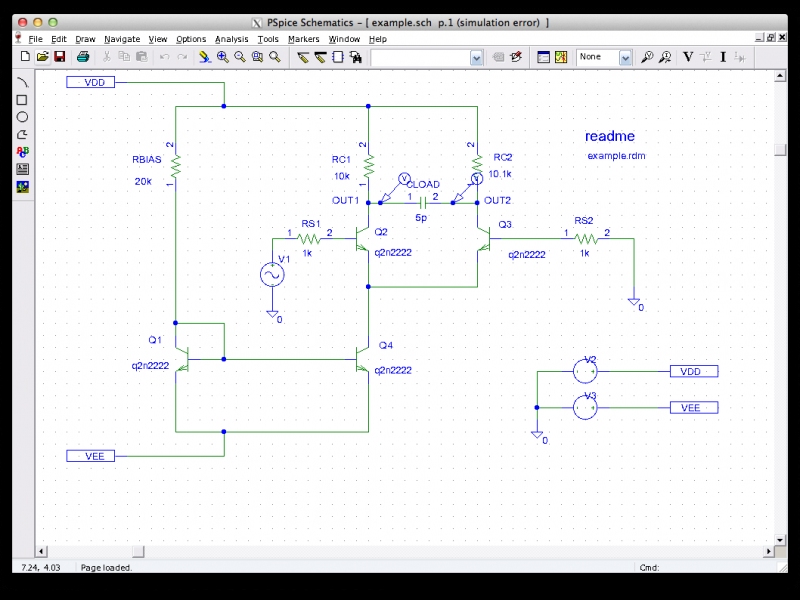
This software package is actually a cost-effective solution when compared to running physical tests on a component and risking real-world damage or downtime. The main intention is to optimise performance while observing variables such as reliability, the effects of temperature and any signal degradation across multiple points. OrCAD PSpice Designer can be used to isolate and analyze single circuits or a group of components. This is a great solution for engineers who are designing a specific device and wish to observe its effects within a virtual environment before implementing it into a real-world situation. OrCAD PSpice Designer is software meant to aid in the simulation and testing of both mixed-signal and analogue circuits.

Softonic review Professional and Advanced Circuit Simulator for Personal Computers


 0 kommentar(er)
